

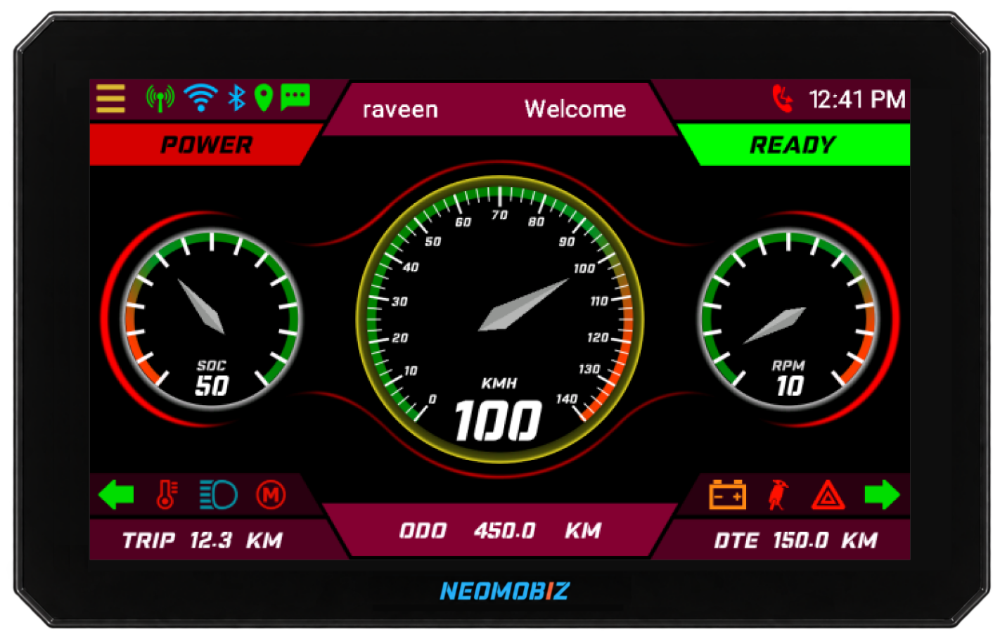
A connected cluster is easy to describe as “a dashboard with connectivity.” That description is too narrow for an OEM architecture decision. The real question is how vehicle information, communications, selected control functions and connected services are partitioned, and who owns each interface over the life of the programme.
What is a connected cluster?
A connected cluster combines the rider-facing instrument display with a communications path to other devices or services. In an electric two-wheeler or three-wheeler, that can include CAN-based vehicle data, Bluetooth interaction with a phone, positioning through GNSS and wide-area communication through 4G.
An Integrated Connected Cluster goes further by coordinating additional vehicle-side responsibilities within the same product architecture. In the Neomobiz implementation, the TFT cluster works alongside telematics, four-channel high-side body control and AVAS capability. Mobile, cloud, fleet and OTA services extend the architecture beyond the vehicle.
A connected display exchanges data. An integrated connected cluster also coordinates functions and lifecycle responsibilities around that data.
Define responsibilities before selecting interfaces
The value of integration does not come from placing more features on a bill of materials. It comes from removing ambiguity between subsystems. OEM teams should define the responsibility of each layer before deciding message formats, connectors or screen flows.
Cluster
Presents vehicle state, energy, warnings, ride modes and connected information according to a controlled HMI hierarchy.
Telematics
Moves authorised telemetry, location, events and commands between the vehicle and connected services.
Body control
Executes agreed high-side control functions while respecting vehicle-state logic and electrical boundaries.
AVAS
Produces configured pedestrian, reverse or vehicle-event sound profiles from agreed triggers.
This partition should remain explicit even when functions share a platform. Integration is not a reason to blur requirements; it is a reason to define them more clearly because display, communications and control behaviour now evolve together.
Map the complete vehicle-to-cloud data path
Every connected feature should have an identifiable source, processing owner, transport path, destination and response behaviour. A live location view, for example, depends on more than GNSS availability. It also depends on wake state, communications availability, cloud ingestion, vehicle identity, user permissions and the application’s refresh behaviour.
For each data item, document:
- the authoritative source and physical or network interface;
- units, scaling, valid range, update rate and timeout behaviour;
- what the cluster shows when the value is invalid or unavailable;
- whether the value leaves the vehicle and for what operational purpose;
- which users or systems may view it or initiate a related command; and
- how the feature behaves during sleep, wake, poor coverage and software update states.
Integration does not remove system boundaries
A consolidated architecture still needs clear electrical, software and operational boundaries. Functions that affect vehicle behaviour should be separated from convenience features in the requirements, even when they are coordinated by the same product platform.
| Boundary | Questions to resolve | Typical output |
|---|---|---|
| Vehicle network | Which ECU owns each signal? What are the timing and timeout rules? | Reviewed CAN matrix and state definitions |
| Electrical I/O | Which loads or events use the body-control channels? What protection is required? | I/O allocation and interface specification |
| HMI | Which information is mandatory, contextual or optional? How are conflicts prioritised? | Screen hierarchy, telltale matrix and alert rules |
| Connected commands | Which actions are permitted, authenticated and supported by the target ECUs? | Authorisation model and command-state handling |
| Lifecycle | How are configurations, firmware versions and vehicle identities controlled? | Release, onboarding and OTA workflow |
Remote controls deserve particular care. A mobile command is only one part of the feature. The target ECU must support the action, the vehicle state must permit it and the OEM must explicitly authorise the full behaviour.
Questions an OEM team should answer early
- What is the target product experience?Define the rider and operational outcomes before choosing individual features.
- Which responsibilities should be integrated?Identify retained ECUs, consolidated functions and the interfaces between them.
- What data is authoritative?Agree signal owners, state definitions and behaviour when data is missing or stale.
- What must remain configurable?Separate programme configuration from software changes that require a new release.
- How will the product be operated?Include onboarding, access control, diagnostics, firmware and support workflows in the architecture.
- How will the complete system be validated?Plan vehicle-level tests across electrical states, HMI behaviour, coverage conditions and connected-service dependencies.
Resolving these questions early gives the connected cluster a stable role in the vehicle. It also creates a cleaner basis for requirements, integration reviews and sourcing comparisons.