

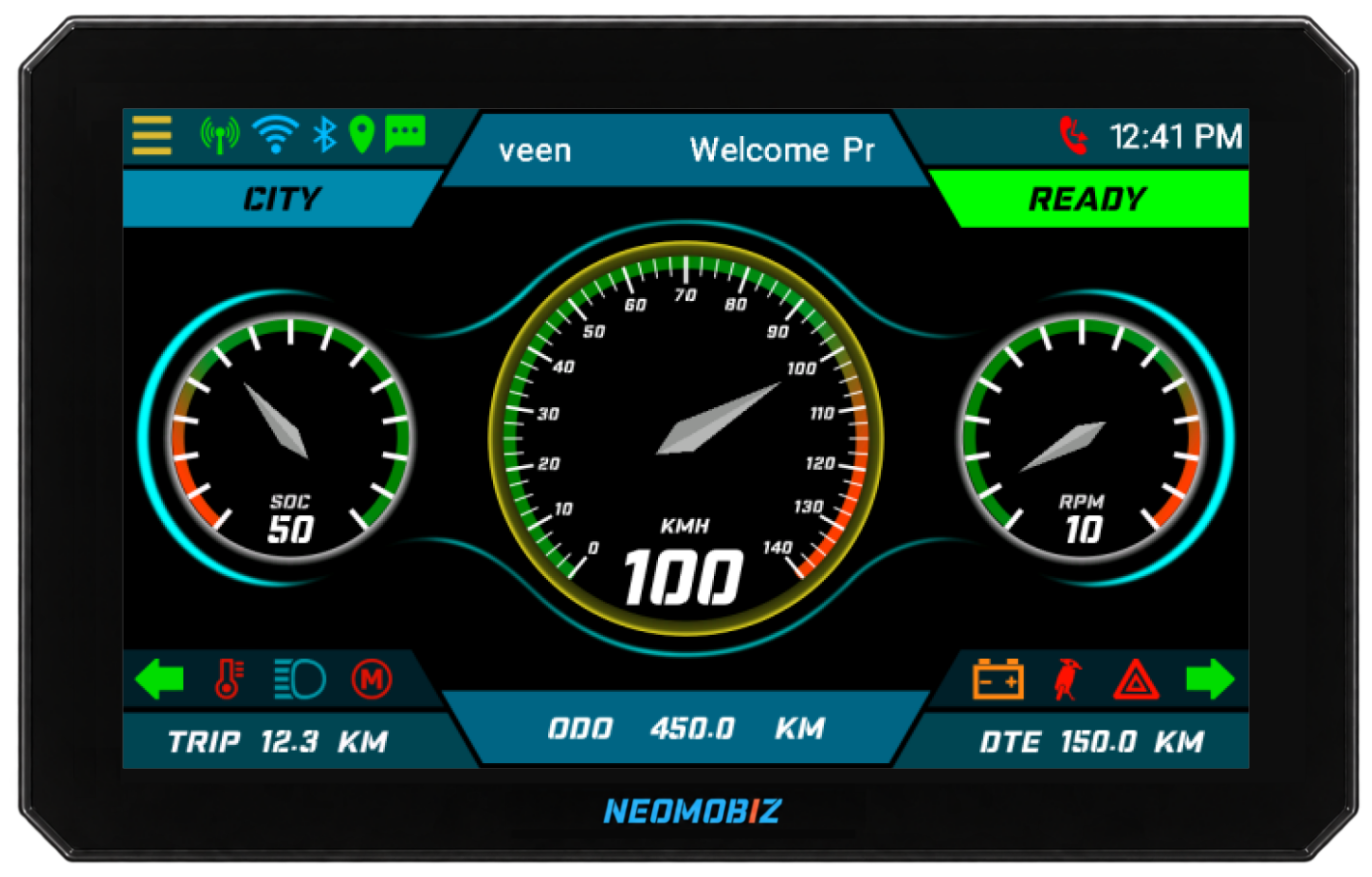
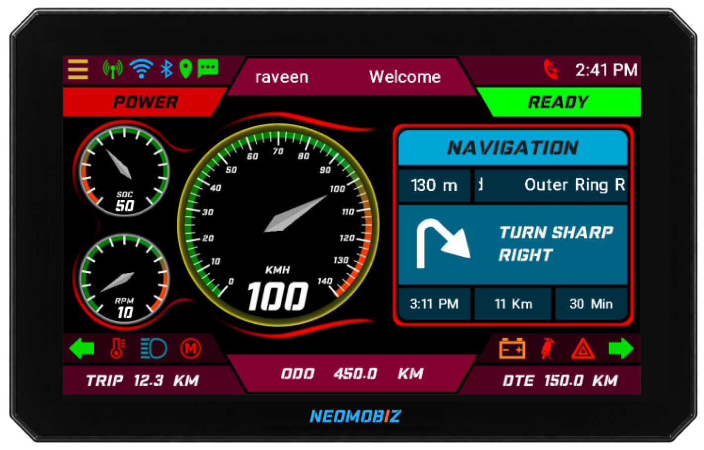
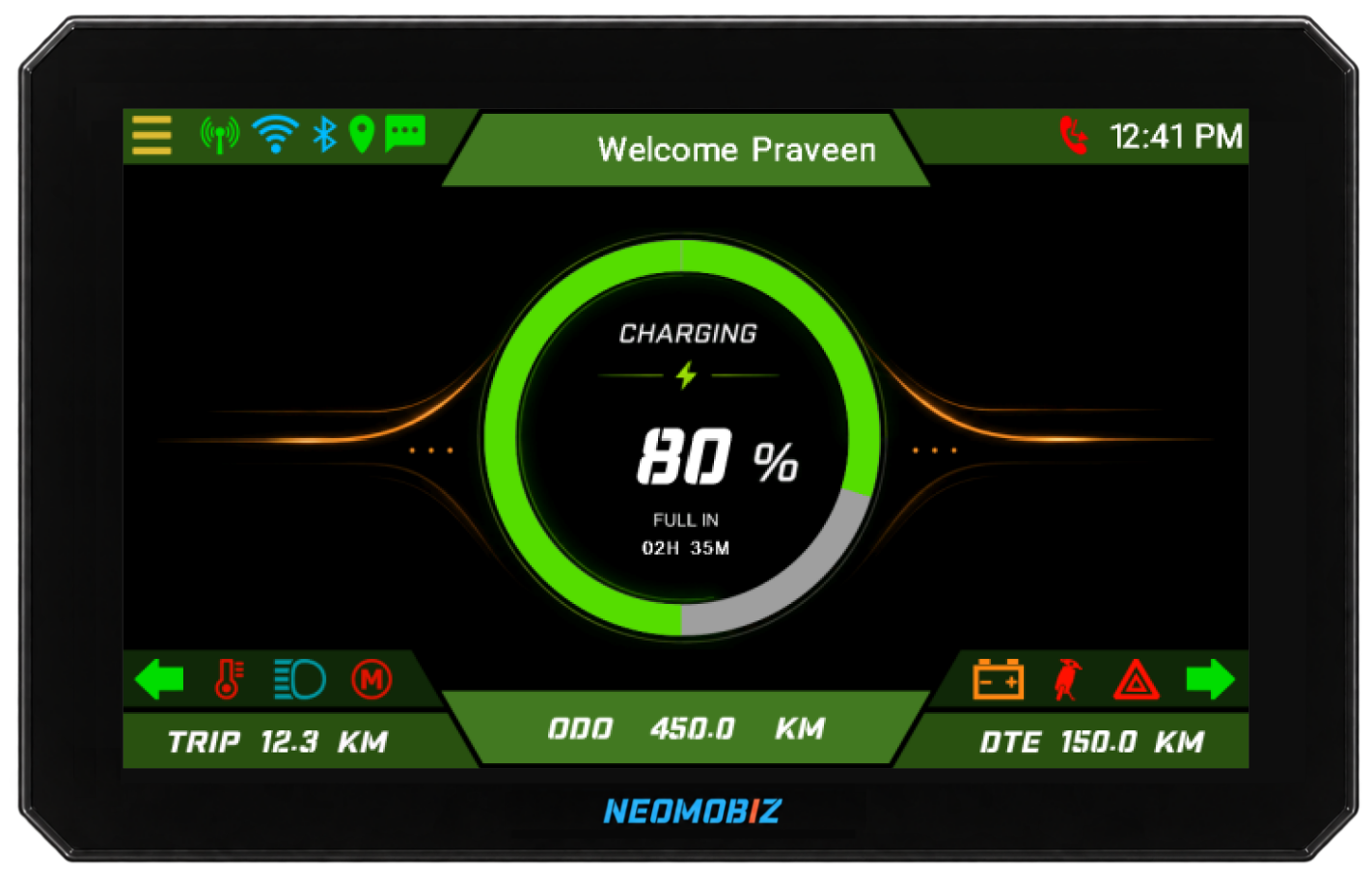
Instrument cluster integration sits at the intersection of mechanical packaging, electrical architecture, embedded software and rider experience. Treating it as a late-stage display task usually exposes unresolved signal ownership and warning behaviour when programme flexibility is lowest.
Define the cluster scope before the screen design
Start with the role of the cluster in the complete vehicle. An electric two-wheeler used for personal mobility may prioritise ride modes, navigation and phone interaction. A three-wheeler used in fleet operations may place more emphasis on state of charge, range confidence, warnings and operational status.
Display direction
Choose TFT or PMVA according to the information set, interaction depth and product positioning.
Viewing conditions
Define rider eye point, mounting angle, ambient-light use cases and glance-critical content.
Vehicle interfaces
Identify CAN, discrete I/O, power states and any connectivity responsibilities owned by the cluster.
Product identity
Agree the visual language, ride-mode differentiation and how branding behaves across states.
Packaging inputs should include the available envelope, mounting strategy, connector access, surrounding trim and service expectations. These decisions affect display selection and mechanical design, so they should be stable before detailed HMI work.
Treat the CAN matrix as a behaviour contract
A signal list describes what data exists. A cluster integration specification must also describe what each value means over time. For every displayed value or telltale, the team needs an owner, scaling, update rate, valid range, timeout and fallback behaviour.
For EV energy information, align at least:
- state-of-charge source, resolution and invalid-value handling;
- estimated-range ownership and the conditions under which it is suppressed;
- charging states, connector states and completion or fault indications;
- drive-ready, park, reverse and propulsion-limited states;
- battery, motor, controller and thermal warnings; and
- sleep, wake and key-state transitions that affect the display.
The cluster needs a deliberate response when a message times out or a value becomes invalid. Reusing the last known value without a defined rule can mislead the rider.
Build the HMI around information priority
The most important cluster design decision is not colour or animation. It is the hierarchy that determines which information is persistent, which appears only in context and which can interrupt another view.
| Information level | Examples | Design question |
|---|---|---|
| Persistent | Speed, drive state, primary energy status | What must remain visible across every ride screen? |
| Contextual | Charging detail, navigation manoeuvre, media | When does the information appear and what replaces it? |
| Advisory | Low energy, service reminder, connectivity status | How is it acknowledged without hiding more urgent content? |
| Critical | Safety or system warnings defined by the programme | What takes visual priority and when may it be cleared? |
Prototype screens should be reviewed with representative vehicle states, not only attractive nominal values. Long text, simultaneous alerts, missing data and transitions between ride and charging modes often reveal hierarchy problems earlier than a polished static mock-up.
Add connected features with explicit dependencies
Navigation prompts, call or message indicators, media information and mobile-app interaction can make a TFT instrument cluster more useful. Each feature also introduces dependencies that should be visible in the requirements.
Connection state
Define pairing, reconnection, loss-of-service and user feedback behaviour.
Power state
Agree which connected services remain available during sleep, charge and key-off states.
Permissions
Make user consent and OEM authorisation part of the feature, especially for remote actions.
When the instrument cluster is part of an integrated connected platform, its display states can stay aligned with the rider app and fleet tools. That consistency still depends on shared definitions for vehicle identity, signal meaning and command outcomes.
Plan validation at the vehicle level
Bench testing can verify messages and screen behaviour, but the cluster is experienced in a vehicle. The validation plan should cover the actual electrical states, viewing conditions, network timing and connected-service dependencies that the rider will encounter.
- Packaging and visibilityCheck the installed viewing angle, occlusion, reflections and readability in representative conditions.
- Power-state behaviourVerify boot, shutdown, sleep, wake, brownout and charging transitions against the vehicle sequence.
- Network robustnessExercise message loss, delayed data, invalid values, bus recovery and simultaneous state changes.
- HMI conflictsTrigger overlapping telltales, warnings, navigation and connected events to confirm priority rules.
- Connected-service lossTest pairing failures, poor coverage, stale cloud data and interrupted update workflows.
- Programme complianceConfirm the OEM’s regulatory, environmental, electrical and product-validation requirements for the target market.
The result should be a traceable set of cluster behaviours tied to vehicle requirements, not only a collection of approved screens. That traceability makes later UI changes and software releases easier to assess.